
Installation sequence and quality control of a ventilated facade
Every layer of a rainscreen hides the previous one, so the order of work is also the quality plan. Here is the sequence, what to check at each stage and which records to collect.
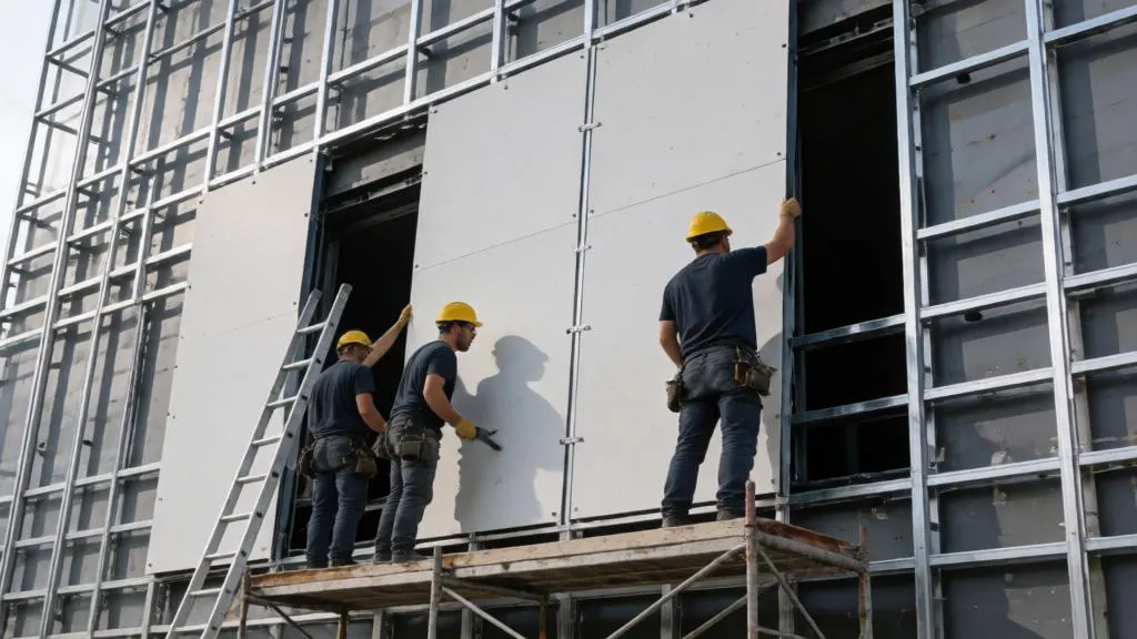
Why the order matters
A ventilated facade is built in layers, and each layer hides the previous one. After the cladding goes on, nobody sees the anchors, insulation joints or fire barriers without taking panels down. The sequence is therefore also the quality-control plan: every stage ends with a check and a record before the next one starts.
Georgia has no separate installation standard for ventilated facades. The sequence below follows the facade project and the requirements of the system supplier, with acceptance organised through the framework described in site supervision. Where this guide names a figure such as a tolerance, the project must state its own value.
Preparation before the first anchor
Installation should not start until these are in hand:
- the approved facade project with calculations and shop drawings, plus the work method statement of the installer;
- a geodetic survey of the real wall. Concrete and masonry walls deviate from the drawings by tens of millimetres, and bracket projections are chosen from the survey to hold both a flat facade plane and the minimum air gap;
- on-site pull-out test reports for the anchors in each substrate, as described in anchors and substrates;
- incoming inspection of materials: marking, profile thickness, alloy and coating, fastener grade, insulation type and fire classification, cladding batch and shade;
- scaffolding or access equipment checked for wind and ice limits.
Substitutions are the most common failure at this stage. A thinner profile, a shorter anchor or a lighter insulation "equivalent" must go through the designer, in writing, before it reaches the wall.
The installation sequence
- Setting-out. Axes, levels and reference lines are transferred from the project, and the real deviations of the wall are recorded.
- Brackets and anchors. Anchors are drilled and set according to the substrate and the test results, with thermal-break pads under the brackets. Anchor torque and embedment are checked.
- Insulation and wind barrier. Boards are fitted tight, with staggered joints, fixed with plate dowels in the quantity stated by the project. The wind barrier is continuous, undamaged and lapped as specified.
- Fire barriers. Cavity barriers go in at the levels shown in the fire strategy, continuous and fixed as tested, with openings left for drainage and ventilation where the design requires. See fire strategy.
- Vertical profiles. Profiles are fixed to the brackets with fixed and sliding points as designed, with expansion gaps at the joints. Alignment is checked on a long straightedge before cladding starts. See movement joints.
- Cladding. Panels, cassettes or tiles are fixed with the specified clips, rivets or screws, with even joints and the agreed joint width. The first row sets the geometry for the whole facade, so it is checked first.
- Junctions and flashings. Window reveals, sills, corners, parapet, plinth and expansion joints are closed with the details from the project. Sills need a slope and a drip edge. See facade junctions.
- Final inspection and handover. Air-gap openings are open, protective film is removed, damaged coatings are repaired, and as-built documents are issued.
Changing the order creates defects that cannot be corrected later. Insulation fitted after the profiles leaves thermal bridges and gaps behind the framing. Cladding fixed without setting-out gives steps in the plane. Cavity barriers added last are often left out.
Quality control by stage
| Stage | What is checked | Record |
|---|---|---|
| Setting-out | Axes, levels, wall deviations | As-built survey drawing |
| Brackets and anchors | Anchor type and embedment, pads, torque, spacing against the project | Hidden-work record, anchor test report |
| Insulation and wind barrier | Tight joints, dowel quantity, continuity of the barrier, damage | Hidden-work record |
| Fire barriers | Position, continuity, fixing | Hidden-work record with photographs |
| Vertical profiles | Alignment, verticality, sliding points, expansion gaps, minimum air gap | Intermediate acceptance of the frame |
| Cladding | Joint width and evenness, flatness, fixing type and count | Final inspection |
| Junctions and flashings | Slopes, drip edges, sealing, open air-gap vents | Final inspection, as-built documents |
Checks that can be done in an hour
- Pull-out test report for the real substrate, not a certificate for the box of anchors.
- Bracket spacing against the drawing, including the corner and edge zones where the project reduces it.
- Insulation continuity: no gaps, no bulges, dowels present.
- Flatness of the profiles on a two-metre straightedge, against the tolerance written in the project.
- Joint width in a sample of cladding rows.
- Air-gap width at the narrowest point and the state of inlets and outlets.
If the contractor refuses to show a hidden layer before it is closed, stop that section until the record exists.
Documents at handover
The handover package is the owner's insurance for the years ahead. It normally includes:
- hidden-work records for anchors, insulation and wind barrier, fire barriers and frame;
- anchor test reports and as-built survey drawings;
- material passports and supplier documents for each batch, including the Declaration of Performance or European Technical Assessment where Government of Georgia Resolution No. 476 of 1 October 2018 applies;
- photographic record of each layer;
- the maintenance plan; see durability.
Weather and working conditions
The system has no wet processes, so work continues in cold weather. The limits are strong wind, ice on scaffolding and rain on exposed insulation. Insulation boards must be kept dry in storage and on the wall until the cladding closes the layer, and open sections should be protected at the end of every shift.
For help with a work method statement or an installation checklist tied to your drawings, contact the design team.
Common sequence errors
| Error | Result | How to prevent it |
|---|---|---|
| Profiles fixed before insulation | Gaps and thermal bridges behind the framing | Hold the sequence; accept insulation before the frame closes it |
| No setting-out survey | Steps in the facade plane, air gap too narrow in places | Survey first, select bracket projections from it |
| Anchors set before testing | Brackets fail in a weak substrate | Test in each substrate; fix to floor slabs where the wall is weak |
| Cavity barriers left for the end | Barriers omitted or discontinuous | Install and record them before the frame |
| All profile points fixed rigidly | Noise, waves in the cladding, sheared rivets | Fixed and sliding points as designed |
| Hidden layers closed without a record | No proof of quality if a defect appears | No cladding on a section without signed records |