
Air gap in a ventilated facade: dimensions, openings and errors
If the air gap closes at the plinth, the window heads or the fire stops, the wall stops drying. This page gives the dimensions, the openings and the details that keep it working.
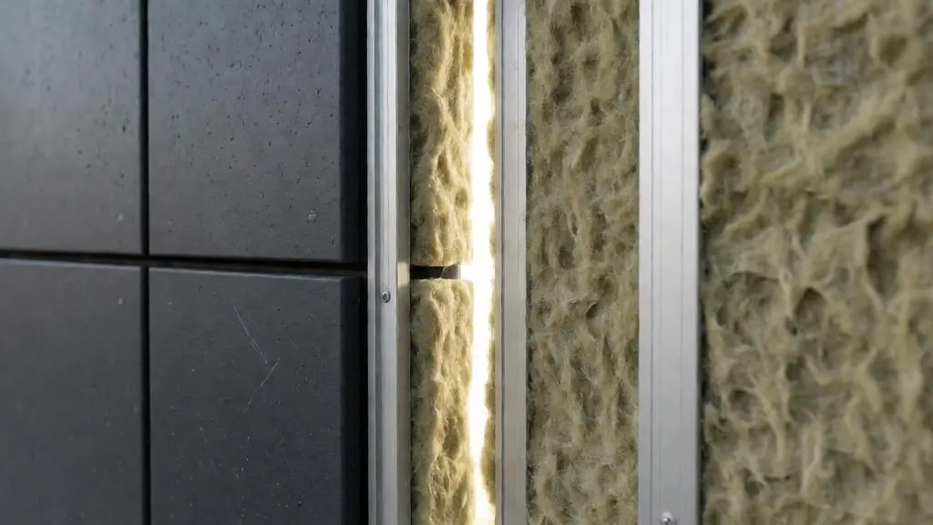
The air gap is the reason a ventilated facade is called ventilated. When it is designed as a dimension on a section and nothing else, it closes up at the plinth, at the window heads and at the fire stops, and the wall loses its ability to dry. This page gives the working dimensions, the openings and the details that decide whether the gap functions.
What the gap has to do
Air moves up the gap because of the temperature difference between the wall and the outside, and because of wind pressure on the facade. On the way it removes water vapour that has passed through the wall and the insulation, evaporates any water that has entered through the cladding joints and takes away some of the solar heat absorbed by the cladding. A dry insulation layer keeps its design thermal resistance, which is the value in the thermal calculation. A wet one does not.
Dimensions used in practice
No Georgian act sets a gap depth for ventilated facades. The figures below are engineering practice, and the final value must agree with the system manufacturer's documentation and with the calculation.
| Parameter | Working value | Comment |
|---|---|---|
| Minimum clear depth | About 40 mm | Measured in the narrowest place, after the wind barrier is installed and with real wall deviations taken into account |
| Typical design range | 40–100 mm | Larger values for taller buildings and longer vertical channels; 60–100 mm is common on multi-storey blocks |
| Upper limit | Around 100–150 mm | A very deep gap strengthens the chimney effect in a fire and adds to the thickness of the facade |
| Measured from | Outer face of insulation or barrier | To the back of the cladding, not to the profile |
The measuring rule matters more than the nominal number. Take a bracket with a projection chosen "just enough" for 40 mm. If the wall bulges by 50 mm in one bay, the gap there is gone. The projection has to include the wall tolerance, the insulation thickness tolerance and the sag of the barrier. See brackets for how projection is built up.
Openings: where the air comes in and goes out
- Bottom. An inlet above the plinth or in the first horizontal joint, usually a perforated starter profile with a mesh behind it.
- Top. An outlet below the parapet capping or the eaves, with the same protection against birds, rodents and wind-driven rain.
- Intermediate. Over windows and doors, below sills and at every horizontal member that interrupts the channel, openings or a bypass route are needed so that air can pass around the obstacle.
The free area of the openings should be sized from the system documentation or an airflow check. A deep gap closed at the top by a solid flashing does not ventilate, whatever the section says.
Fire stops without killing the ventilation
Resolution No. 41 of 28 January 2016, the Building Safety Rules based on the International Building Code, does not use the term ventilated facade. Its Chapter 14 on exterior walls asks for evidence that the whole wall assembly behaves acceptably, including NFPA 285 testing for buildings above 12 m with a combustible water-resistive barrier. The gap is part of that assembly.
In practice this means:
- Use non-combustible insulation and a barrier with documented fire behaviour.
- Where the design calls for fire stops in the cavity, take them from a tested detail. A continuous solid closure across the whole depth stops the flow for good; a perforated or slotted non-combustible profile with a defined free area keeps a path open in normal service.
- Keep the gap depth within the tested range of the system.
Decide the fire stop positions and the free areas together, on the same drawing. Details are in the fire strategy and in the guide to Resolution No. 41.
Joint type changes the picture
With open joints between panels, some air also enters and leaves through the cladding itself, and rain reaches the barrier more easily. With tight joints, all the exchange happens at the openings, so their free area matters even more. State the joint type in the project and size the openings accordingly.
Five errors we see in submitted designs
- Insulation thicker than designed, or fixed with bulges. The gap falls below the minimum in places. Specify thickness tolerance and require flat fixing of slabs.
- No inlet or outlet. Starter and capping profiles are chosen from the look and are solid. Both must be perforated or have a defined gap.
- Horizontal members across the channel. Sills, intermediate rails and fire stops block the flow. Leave a free bypass or openings.
- No mesh. Birds and rodents nest in the gap and block it. Fit mesh or perforated profiles at every opening.
- Solid fire stops over the full depth. They are drawn once per storey as a precaution and ventilation stops at each one.
All five are cheap to fix on the drawing board and expensive once the cladding is up.
Georgian conditions to design for
- Driving rain. The construction climatology regulation (Annex 5 to Government of Georgia Resolution No. 71 of 15 January 2014) lists oblique rain among its climate data. Use it to decide how much water the joints will let in and whether the barrier needs to be of the exposed-joint grade.
- Coast. In Batumi, salt-laden air enters the gap along with the ventilation. Choose subframe materials for that environment, see profiles and alloys.
- Hot summers. Dark cladding surfaces heat up to 60–80 °C, and the gap should be open enough to carry some of that load away.
Checklist for the designer and the inspector
- Clear gap depth stated for the narrowest section, not the nominal one.
- Bracket projection includes wall deviation and barrier sag.
- Inlet at the base and outlet at the top shown on the node drawings with free area.
- Bypass around window heads, sills and horizontal rails.
- Mesh or perforated profile at every opening.
- Fire stops are from a tested detail and are ventilated or positioned so that flow is kept.
- The barrier is fixed so that it cannot belly into the gap.
On site, check the gap before the cladding closes it: with a gauge at several points per storey and after the insulation is fixed. Then read how the whole system works or send us the project for review.