
Ventilated facade junctions: windows, corners, plinth and parapet
Most facade defects appear at junctions. This page lists what each junction must do, the typical failures and what the drawing set must show.
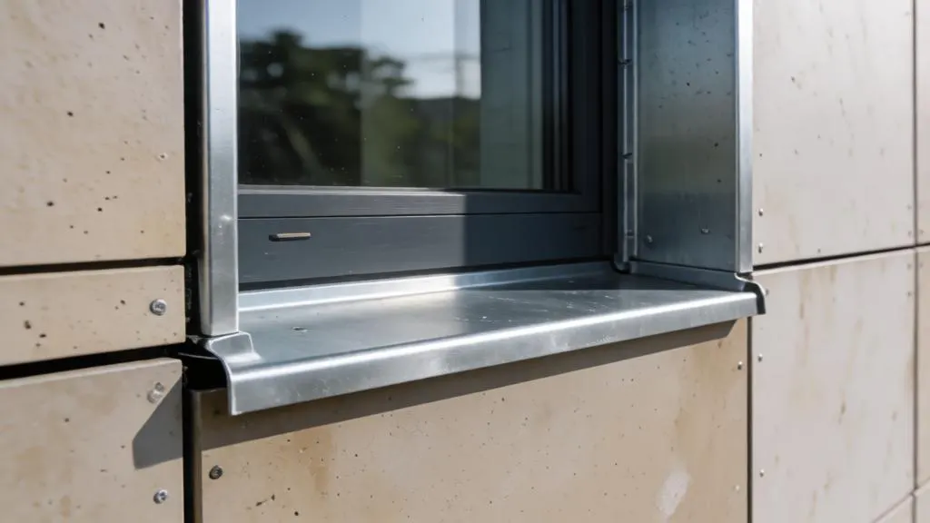
A ventilated facade lives in its junctions. Window and door surrounds, external and internal corners, the plinth start, the parapet cap and the building movement joints are where wind, water, heat and fire requirements meet. This is also where most defects appear. The notes below cover what each junction must do and what the drawing must show.
Why junctions get their own drawings
On a flat wall the system repeats: the same bracket, the same rail, the same panel. At a junction the repetition breaks and someone has to decide what continues, what stops and what is added. If those decisions are left to the installer, the result depends on habit. In a proper project every junction is drawn separately as a section and a plan detail, and the installer works from the drawing. Ask for the junction album before work starts; the content of that package is described in shop drawings for ventilated facades.
Junction map
| Junction | Main task | Typical failure |
|---|---|---|
| Window and door surround | Close the cavity, carry water away, avoid a cold bridge round the frame | Frozen or damp reveal; water behind the sill flashing |
| External corner | Take higher wind suction, hold panel edges | Corner profile under-designed; panels loosened by pressure peaks |
| Internal corner | Keep both rails straight, allow movement | Rails blocked against each other |
| Plinth / base start | Start the system, protect insulation from splash and pests | Closed cavity inlet; wet insulation at the bottom |
| Parapet and roof edge | Close the top, drain water outwards | No coping or flashing, water runs into the insulation |
| Building movement joint | Let the building move without loading the facade | Subframe bridging the joint |
| Floor-level and opening fire stops | Interrupt the cavity where the fire strategy needs it | Barrier left out or blocking all ventilation |
Windows, doors and reveals
The window junction has three jobs. It must close the cavity around the opening so that insulation is not exposed, it must shed water at the sill, and it must keep a continuous layer of insulation around the frame so that the reveal does not become a cold bridge. A badly made reveal shows up as freezing along the opening contour.
- Frame position. The window can sit in the wall plane or be moved outwards into the insulation layer. The second option reduces the thermal bridge, but it needs brackets or a support frame for the window, and it is agreed with the window supplier at the design stage.
- Reveal depth. A thick facade makes a deep reveal. Beyond roughly 250 mm depth, additional reveal elements are normally needed. The depth follows from the total build-up (see facade thickness), so windows and sill flashings must be ordered after that thickness is fixed.
- Sill flashing. Sloped outwards, with a drip edge that projects beyond the cladding face, and with end upstands so that water does not run behind the side reveals.
- Seals. A vapour-open weather seal on the outside of the frame and an airtight seal on the room side. Sealant alone is not a flashing.
- Lintel. The cavity above the opening needs a path for air and water; a closed lintel traps moisture.
External and internal corners
Wind suction rises near external corners. The corner zone uses a smaller bracket spacing or a stronger rail section, and the load assumptions come from the wind calculation, not from the typical field. The corner profile or the folded cassette edge must be fixed so that it does not flutter, and the panels on both sides must be able to expand away from the corner.
At internal corners two rail lines meet. Keep a gap between them so that neither blocks the thermal movement of the other (see movement joints).
Plinth and base
The plinth start is the lowest point of the cavity and the place where water splashes up from the pavement. A usual solution is a starter profile with a perforated closure, so that air can enter but insects and rodents cannot, with the insulation and membrane protected below. The cladding stops above ground level at a height that suits the splash and the snow in that location. The plinth wall itself is often a different material (render, stone or concrete), so the transition needs a drip and a defined joint.
Air inlets and outlets at the base and the top determine whether the cavity actually ventilates. Sizes and mistakes are covered in the air gap article.
Parapet and roof edge
At the top the cavity is closed with a ventilated cap, and the parapet is covered with a coping that overhangs the cladding. Without a coping water enters the insulation from above. The coping is fixed to the parapet structure and not to the cladding, with slope towards the roof or with a drip on the outer side. Parapets are also non-structural elements for the seismic check, so their fixing to the structure is calculated (see seismic design).
Fire stops at junctions
Where the project needs to interrupt the cavity (at floor levels or round openings), the barrier is part of the junction detail. The fire rules are in Government of Georgia Resolution No. 41 of 28 January 2016, Chapter 14, which requires a wall assembly test to NFPA 285 for a combustible water-resistive barrier on buildings above 12 m (Resolution No. 41 on matsne.gov.ge). A barrier must not close the ventilation completely, so its design is coordinated with the air gap. See fire safety under Resolution No. 41.
Building movement joints
A movement joint in the building must continue through the facade. The subframe is interrupted at the joint and does not transfer forces across it. Rails end on both sides, the joint is covered by a flexible cover profile, and the insulation and membrane are detailed so that the joint stays weather-tight when it opens and closes. In a seismic city such as Tbilisi the width of the joint follows the structural designer's figures.
Thermal bridges at junctions
Every junction adds linear thermal bridges: window frame, sill, plinth, parapet. Under Government of Georgia Resolution No. 354 of 13 July 2021 the wall U-limit is 0.50 / 0.38 / 0.25 W/m²K for climate zones 1 / 2 / 3 (Batumi / Tbilisi / Tianeti); as amended, current consolidated text on matsne.gov.ge. The junction details are part of the thermal calculation, not an afterthought (thermal calculation).
Junction checklist for the drawing set
- Section and plan for every window type: frame position, insulation wrap, flashing, seals.
- Corner details with bracket spacing and rail section.
- Plinth start with air inlet area and insect mesh.
- Parapet with coping, drip and fixing to the structure.
- Movement joint covers and the points where rails stop.
- Fire barrier positions and their relation to the air gap.
- Material list and fixing schedule for each detail.