
Facade shop drawings: layout, cutting lists, marking and schedules
The sheets the installer actually works from, how parts are marked, and a practical test of whether a set is detailed enough.
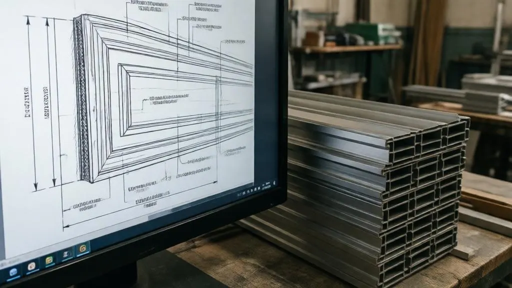
Shop drawings turn a designed facade into something that can be ordered, cut, delivered and assembled without guessing. They are the sheets the installer, the buyer and the site engineer actually use. This page lists what they contain, how panels and parts are marked, and how to judge whether a set is detailed enough.
Why the level of detail matters on site
Installation happens at height, in wind, to a schedule, often with several crews. If fixings and nodes are described only "in general", each crew fills the gaps its own way. The consequences are familiar: an uneven plane, mixed-up fasteners, rework and arguments about responsibility. On a large facade the error repeats across the whole elevation.
A detailed set removes that uncertainty. The installer works from a drawing, not from memory of the last job, and installation becomes the assembly of a kit.
The practical test of completeness
A set is detailed enough when an installer can point at the sheet and say where each rivet goes, at what pitch, how a corner node differs from a normal one, and how the kit is marked. If any of these questions has no answer on paper, someone will invent the answer on the scaffold.
What the set contains
| Sheet group | Content | Used by |
|---|---|---|
| Facade elevations with marking | Every cladding element, rail and bracket position with its mark; openings, corners, joint pattern | Site crew, site engineer |
| Bracket and anchor layout | Position and type of each bracket, anchor type per wall zone, reinforced edge and corner zones | Crew, anchor test team |
| Panel layout | Panel or cassette sizes, joint widths, cut panels at edges, orientation | Procurement, workshop |
| Cutting lists | Every panel and profile with dimensions, quantity, holes, hems, finishing | Workshop, supplier |
| Node drawings | Plinth, parapet, corners, windows and doors, reveals, sills, balcony slabs, fire breaks, movement joints, with fasteners | Crew, supervision |
| Fastener and bracket schedules | Type, size, material and quantity of each fixing and part | Procurement, storekeeper |
| Installation notes | Order of work, tolerances, hidden works to be inspected | Site engineer, supervision |
These sheets are produced from the approved design (see design documentation). If the cladding or the wall base changes, the structural calculation has to be checked before the drawings are reissued.
Panel layout: the work that saves the most
The layout starts from the architect's joint pattern and from the real dimensions: openings, slab edges, corners. The designer then does four things:
- Divides each elevation into modules so that standard panels dominate and cut panels fall in places where they are least visible.
- Aligns joints with window edges and floor levels where the architect asked for it, and says so on the sheet.
- Checks every format against the wind load in edge zones (thin cassettes need a stiffness check; see structural calculation).
- Allows for the difference in layer thickness where two claddings meet.
The aim is that panels are cut in the workshop rather than adjusted on the scaffold. Field cutting of coated metal or laminate also damages edges and coatings.
Marking: one scheme from drawing to scaffold
Every item has a mark that appears on the elevation, in the cutting list and on the label. A simple scheme is enough, for example facade, level and position: F2-L07-P014 for facade 2, level 7, panel 14. The convention itself does not matter; what matters is that it is the same on the drawing, the order, the packing list and the item, and that the label survives transport.
Pack and deliver by zone and floor, in the order of installation. A crew that opens a pallet and finds the panels for the right floor in the right sequence works faster than one that searches.
Schedules for ordering
The schedules are derived from the calculation, so bracket pitch, rail section and anchor type match the design. This gives a purchase list without a reserve "just in case". Ordering from a calculated schedule normally reduces both shortage and surplus; ordering from an area and a rule of thumb usually does not. Add a deliberate allowance only for cut panels, and write it into the schedule.
Nodes: draw the ones that cause problems
Most defects on site come from nodes nobody drew. The ones to cover in every set:
- cladding turn around window reveals, sill and head, with the flashing;
- external and internal corners, including the reinforced corner zone;
- parapet, with the ventilation outlet and the cap;
- plinth, with the ventilation inlet and the start profile;
- passing a balcony slab or another projection with the subframe;
- movement joints of the building and of the facade (movement joints);
- fire breaks in the air gap where the fire strategy requires them (fire strategy).
More on the geometry of typical junctions is in facade junctions.
Link to the work method statement
Detailed drawings make the contractor's work method statement useful. Stages, material needs and the order of zones follow from the sheets, and the document becomes a working plan for the crew instead of a paper for permission. If several crews work on the same building, a single set prevents different readings of corners, pitch and sequence.
Where a model helps
When the facade is built in a 3D model, the subframe, fasteners and cladding share one geometry. Cutting lists and schedules are then exported from the model, and clashes with slabs, windows and services show on screen instead of on site. See BIM and Revit.
Revisions on site
Surveys of the built structure often differ from the drawings by tens of millimetres. Agree in advance who measures the wall, when, and how the result reaches the drafter. Each reissued sheet carries a revision number and a short note of what changed, and superseded sheets are withdrawn from the site, not left in the crew's cabin.
Common shortfalls in shop drawings
- Nodes drawn at a typical level only, with no corner or special case.
- Marks on the drawing that do not match the marks on the item.
- Cutting list produced from the architect's dimensions, not from the surveyed wall.
- No change log, so the site works from an old revision.
- Schedules not updated after the cladding format changed.
If you already have a design and need only the working set, send it with the survey and the order list through the contact page.