
Ventilated facade design documentation: contents and stages
What goes into a facade design package, how it maps onto the Georgian permit stages, and how to tell a working design from a presentation.
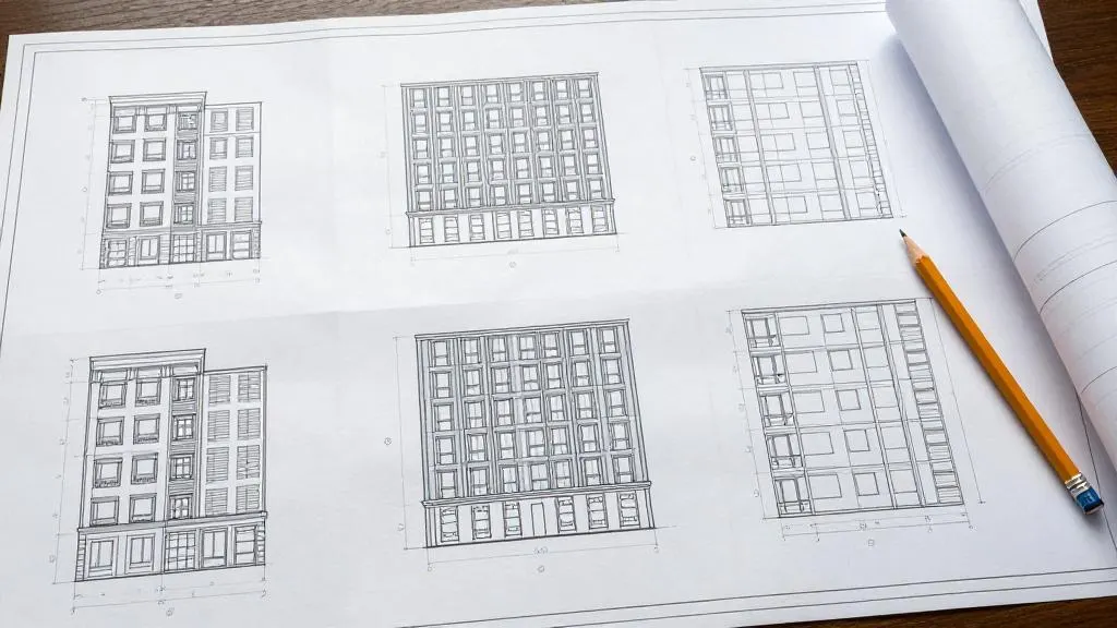
A sketch from the architect is not a facade design. A ventilated facade carries wind, its own weight and, in Georgia, seismic action, so it needs calculations, nodes and schedules that someone is responsible for. This page explains what the facade design package contains, how it maps onto the permit stages, and how to tell a working design from a presentation.
Do you need a design at all?
There is no Georgian national standard dedicated to ventilated facades, so the requirement comes from the general framework. The Code of Georgia on Spatial Planning, Architectural and Construction Activities (Law No. 3213-რს of 20 July 2018, "the Code") makes the author of the design responsible for compliance with technical regulations. Facing work on an existing building that does not significantly change its dimensions or appearance needs no permit under Government of Georgia Resolution No. 255 of 31 May 2019 ("Resolution No. 255", Article 4, paragraph 3), but the facade still has to be engineered: no permit does not mean no calculation.
For new buildings and reconstruction the facade is part of the permitted design and the expert will ask for it. See permits and expert review.
Stages in the logic of the Code and Resolution No. 255
The Code and Resolution No. 255 describe the project in stages: architectural sketch, architectural design and detailed architectural design, and for the structures a structural scheme and a structural design. The permit itself is issued in two steps: conditions for use of the site first, then the construction permit (Code, Article 101). Expert review of the detailed architectural design is mandatory for classes III and IV, and of the structural design for classes II to IV (Resolution No. 255, Article 21). Check the current consolidated text; the resolution has been amended several times.
The facade design follows the same logic in three levels of detail:
| Level | Purpose | Content |
|---|---|---|
| 1. Concept | Agree the system with the architect and developer | Cladding and subframe options, weight, fire evidence, layout principles (system selection) |
| 2. Design for review | What the expert checks | Explanatory note, loads and structural calculation, thermal and fire sections, principal nodes, schedules of main materials |
| 3. Working documentation | What the contractor builds from | Marking plans, every node, cutting lists, fastener schedules, installation notes (shop drawings) |
On small buildings levels 2 and 3 are sometimes merged. The logic does not change: justified decisions first, detailing second.
Who signs what
Under Article 98 of the Code, for classes II to IV the architectural design is signed by an architect and the structural design by a design engineer. The author answers for compliance with the technical regulations. For class I any person may be the author. The mandatory certification of architects and engineers (Article 140) is currently suspended until 20 December 2026 by Law No. 1641-Vმს-XIმპ of 9 June 2026; the date has been extended several times, so check it again at submission.
What the package contains
| Section | What it contains |
|---|---|
| Explanatory note | Initial data, description of the system, justification of the decisions, list of norms and documents used |
| Structural calculation | Loads (dead weight, wind, seismic), checks of cladding fixings, rails, brackets and anchors; see structural calculation |
| Thermal calculation | Insulation thickness and U-value including bracket thermal bridges (thermal calculation) |
| Fire section | Cladding, insulation, membranes and fire breaks against Resolution No. 41 (fire strategy) |
| Elevations and marking plans | Layout of cladding and subframe on every facade, with openings, corners and joints |
| Nodes and details | Plinth, parapet, external and internal corners, windows and doors, fire breaks, movement joints |
| Schedules and specifications | Rails, brackets, fasteners, insulation, cladding with grades and quantities |
| Installation instructions | Technology, tolerances, quality control, hidden works to be inspected |
| Anchor test programme | Where and how many pull-out tests, and the acceptance criterion, when the wall base is uncertain |
What the architectural section must leave open
The architect's facade drawings fix the look: layout of joints, colours, the position of openings. The facade designer needs from the architect:
- the joint pattern and any rules for alignment with window edges;
- approved cladding (or an agreed list of alternatives);
- wall construction, slab edges, balconies, parapet and plinth levels;
- the insulation thickness required by the thermal section.
Anything the facade design changes (a joint moved to suit the cladding module, a projection) goes back to the architect for approval; keep the log of such changes.
How to recognise a working design
Use this checklist before you sign a contract or accept the package:
- The calculation uses the data of your building (city, height, wall base), not a typical case.
- Anchors are tied to the actual wall material, with a test programme where the base is unknown.
- All junctions are drawn: plinth, parapet, corners, openings, joints.
- Schedules agree with the calculation: bracket pitch, section, quantity.
- Fire evidence for each layer of the wall assembly is listed.
- Author's supervision during installation is provided for.
An hour spent on this list is the cheapest audit a facade will ever get. A package of three sheets and a logo is a presentation, not a design.
Changes after approval
Facade designs change: the developer swaps the cladding, the architect moves a window, the wall turns out to be hollow block instead of brick. Each change has a cost in the calculation, not only in the drawing. We keep a revision log and repeat the affected checks (weight, wind zones, anchors) before the working documentation is reissued, so the site never works from a superseded sheet.
Sample designs from another building
A sample package is useful to check the structure of the documents. As working documentation it is not usable: loads, wall base, heights and cladding differ for every building, and a design copied from another site will not pass review or protect you in a dispute.
What is needed to start
Elevations or measured drawings, the address, the wall material and the preferred cladding are enough to begin. The full list is on what to send for a calculation. The output is the package above in PDF and DWG, a material schedule for procurement and a node album for the installers; send the drawings through the contact page.