
BIM and Revit for ventilated facade design: model, clashes, schedules and cutting lists
A facade has thousands of repeated parts, and a 3D model keeps their number, position and mark consistent. This article explains what we model, at which level of detail, and what is taken from the model into the drawings and production.
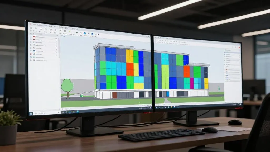
Why model a facade
A ventilated facade is the part of a building with the most small components: brackets, profiles, panels, fixings, fire stops, reveal parts. In flat drawings the quantities are counted by hand and typically contain errors, which then show up as missing parts, idle crews or leftover material on the site. A model produces the schedule and recalculates it after every change.
Three practical benefits stand out.
- Clashes found on screen. Brackets hitting windows, fire stops cutting through ducts, profiles meeting balcony slab edges.
- One source for the drawings. Layout, sections, details and schedules come from the same model and do not diverge.
- Real geometry. Panel layout with true joint widths and details in 3D that an installer can read without interpreting.
Status in Georgia
No Georgian act makes BIM mandatory for facade design, and there is no Georgian standard for BIM of facades. The Construction Code and Resolution No. 255 require the drawings and the calculations; how they are produced is up to the designer. If the client asks for BIM, EN ISO 19650 is the usual reference for information management, and the model requirements are written into the client's BIM execution plan. The model does not replace the set of drawings that is submitted for review; see design documentation.
Level of development by stage
| Level | What the model contains | Used for |
|---|---|---|
| LOD 200 | Overall dimensions of the system, panel layout, build-up thickness | Coordination with the architect, system selection |
| LOD 300 | Accurate subframe geometry, nodes, quantities | Design for review and tender; basis of the structural calculation |
| LOD 350 to 400 | Every bracket, profile, panel and fixing with marks | Shop drawings, ordering, cutting lists, installation |
| LOD 500 | As-built model | Handover to the building operator |
The level is agreed with the client at the start; modelling everything at LOD 400 from the first week is a waste on a project that is still in the concept stage.
How we build the model in Revit
- Input. The architectural model (IFC or Revit link), facade elevations, survey data of existing walls. For a refurbishment a scan or measured survey is the better base than the old drawings.
- Grid and panel layout. Horizontal and vertical modules from the architectural intent, adjusted to openings, corners and movement joints.
- Subframe. Families of brackets, profiles and fixings with the real cross-section, material and mass, so the schedule gives metal weights and counts.
- Cladding. Panel families with parameters: format, thickness, mark, fixing type, edge zone.
- Nodes. Windows, reveals, parapet, plinth, corners and fire stops modelled as typical assemblies and then placed.
- Checks. Clash detection against architecture, structure and services; a check of the model data against the calculation.
Parametric families make a change cheap: when the panel height changes, the schedule and the elevation change together.
Model and calculation
The structural calculation takes its inputs from the model: real spans, bracket positions, the number of fixing points, the wind zones of the facade. The reverse is just as important: the result (bracket spacing, profile section, anchor type) goes back into the model as parameters. A calculation made on a simplified bay and a model with different spacing is a common source of mismatch. For the load cases see structural calculation, for earthquake effects seismic design.
Wind, seismic and thermal data come from Georgian regulations (Resolution No. 71 and Resolution No. 354), and the model is not a source of norms. It is a tool that stores which values were applied to which part of the facade.
Clash detection: what usually shows up
| Clash | Typical consequence on site |
|---|---|
| Bracket position meets a window frame or a reveal | Bracket moved ad hoc; spacing no longer matches the calculation |
| Fire stop crosses a duct or pipe fixed to the wall | Fire stop cut or left out |
| Profile line crosses a balcony slab edge or a drip | Profile joint in the wrong place |
| Panel joint falls on a movement joint of the building | Cracks, jammed panels; see movement joints |
| Insulation thickness greater than the window installation depth | Reveals of the wrong depth, no space for the sill |
| Anchor point falls into a joint or an opening in the wall | No substrate for the anchor; see anchors and substrates |
Run the check every time the architectural model is updated, not once. Write the open clashes into a list with an owner; the architect, the structural engineer and the facade designer each resolve their part.
What comes out of the model
- Plans and elevations with marks of panels and subframe parts.
- Sections and details cut from the model; details that do not exist in 3D are drawn in 2D and linked to the views.
- Schedules: brackets, profiles by length, fixings, panels by mark, insulation, fire stops. Mark formats are in shop drawings.
- Cutting lists for profiles and panels exported in a table format for the workshop or the cladding manufacturer, with lengths, hole positions and cut-outs.
- Installation scheme with the sequence and the bracket line setting-out coordinates for the surveyor.
The cutting list is only as good as the model data, so the order of production should be preceded by a check of: the sizes against the as-built condition of the wall, the tolerances, and the available format of the board or sheet.
Pitfalls
- Modelling only the visible cladding, with the subframe left to "be solved on site".
- Different levels of detail in different parts of the model, so the schedule undercounts.
- Marks assigned by hand, not as parameters, so a copied panel carries the wrong mark.
- Exporting an IFC with the families converted to proxies and no parameters; agree on the export settings before the first exchange.
- Ordering from the model without checking the actual wall: a model of the design intent is not a survey.
- Treating the model as final while the drawings submitted for review show a different state; keep both on one revision.
What to send us
The architectural model (IFC or Revit) or at least the facade drawings and the survey; the planned cladding and subframe; the level of development and the BIM requirements of the client, if any. A fuller list is in what to send. To discuss a project, use the contact page.