
Brackets for ventilated facades: types, projection, materials and thermal breaks
The bracket carries the cladding, resists the wind and sets the air gap, and it is a point thermal bridge. Here is how to choose and check it.
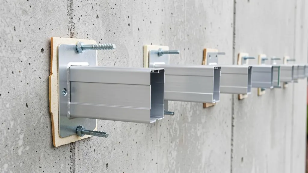
The bracket is the part of the subframe that touches the wall. It carries the weight of the cladding and subframe, resists wind suction and pressure, and sets how far the cladding stands from the wall. It is small, there are hundreds of them on a facade, and most failures and thermal losses of a ventilated facade start there.
Load-bearing and supporting brackets
| Type | Role | Behaviour |
|---|---|---|
| Load-bearing (fixed point) | Carries dead load of the vertical profile and its cladding, plus wind | Fixes the profile vertically; the profile hangs from it |
| Supporting (sliding point) | Takes wind load only | Lets the profile move vertically with temperature changes |
A typical vertical profile has one load-bearing bracket and several supporting ones. The load-bearing bracket is usually in the middle of the profile length or at a level chosen so that the expansion of the profile is shared between both ends, which is detailed in movement joints. If every bracket is fixed rigidly, the profile has nowhere to go in summer and the cladding waves.
Projection: how to choose it
Projection is the distance from the wall to the face of the bracket leg that carries the profile. In practice it falls between 90 and 230 mm. It is the sum of four parts:
- insulation thickness from the thermal calculation;
- clear air gap, for example 40–60 mm;
- adjustment reserve for wall deviations, which can be 100–150 mm on poor walls but is usually much less on new concrete;
- the thickness of the profile's fixing leg, where it is not already included.
Example: 100 mm insulation, a 40 mm gap and 20 mm of reserve call for a bracket of about 160 mm. The longer the leg, the more it bends under load. Past a certain projection the bracket needs a reinforcing rib, a heavier section or a double bracket, and the spacing falls. That is why a very thick insulation layer is not only a thermal choice but a structural one. See facade thickness.
Forms of bracket
- L-shaped. The common form for light and medium cladding and short projections.
- With a rib or a U-section. For longer projections, where bending of the leg governs.
- Double or paired. Heavy cladding such as stone, and the corner and top zones where loads peak.
- Adjustable in two directions. Slotted holes in both legs let the installer set the plane of the profiles without shimming.
Whatever the form, the fixing to the wall must be at the point the calculation assumed. A bracket moved sideways to avoid a hollow cell changes its eccentricity and its load on the anchor.
Materials
| Material | Advantages | Limits |
|---|---|---|
| Aluminium alloy (6xxx series) | Light, does not rust, easy to extrude into ribbed sections | High conductivity, so it needs a thermal break; larger thermal movement than steel |
| Galvanised steel, coated | Stiff, strong, low thermal expansion | Cut edges and scratches are weak points; heavier |
| Stainless steel, A2 or A4 grade | Long life, low conductivity, good for coastal and aggressive air | Cost; the heaviest option |
The conductivity numbers drive the thermal bridging. Aluminium is on the order of 160–200 W/mK, structural steel around 50, stainless steel around 15. A stainless bracket loses far less heat than an aluminium one of the same shape, which is why it is chosen on facades with thick insulation even when the strength is not decisive. A thermal break pad under any bracket cuts the loss further, and it also seals unevenness between the bracket and the wall. The effect should be calculated, not assumed: point thermal bridges are included in the U-value with the method of EN ISO 10211, and the result is compared to the limit in Government of Georgia Resolution No. 354 of 13 July 2021 (0.50, 0.38 and 0.25 W/m²K for zones 1, 2 and 3, as amended; current consolidated text on matsne.gov.ge). See thermal calculation.
Mixed metals in one assembly need isolating washers or pads. Details are in profiles and alloys.
Spacing is a calculation result
Bracket spacing is not taken from a catalogue by habit. It follows from dead load, wind suction in each zone of the facade, the bracket's tested capacity in each direction and the pull-out capacity of the anchor in the actual wall. Corner and edge zones see much higher suction than the middle of the wall, often 1.5 to 2 times, so the spacing there is closer or the bracket is reinforced. The calculation is described in structural calculation. Wind input comes from the construction climatology regulation, Annex 5 to Government of Georgia Resolution No. 71 of 15 January 2014. EN 1991-1-4 and EN 1999-1-1 are the usual European references for the method; they are not mandatory in Georgia, so agree their use with the reviewer at the start.
In seismic zones the bracket, the profile and the anchor are checked together for the seismic action. Annex 3 to Resolution No. 71 requires non-structural elements whose failure can hurt people to be verified with their supports. Tbilisi and Kutaisi are 8 points on MSK-64, Batumi 7. A bracket that holds in a wind check can still fail in a lateral seismic load if its fixing leg is thin.
What to require from the supplier
- Declaration of performance and marking in line with Government of Georgia Resolution No. 476 of 1 October 2018, and a European Technical Assessment for the subframe system where one exists.
- Test or calculation data for the bracket's capacity in each direction, including a combination of loads.
- Alloy designation and temper, or steel grade and coating, written on the drawing.
- Thermal break pad: material, thickness and the thermal conductivity value.
- Slotted holes for adjustment and the range they allow.
- Material certificates for each delivery.
Home-made angles cut from stock sections are not an alternative. They have no documented capacity and no controlled tolerances.
Mistakes that recur
- Spacing set by analogy with another building.
- Projection chosen without a reserve for wall deviation, so the gap shrinks.
- All brackets fixed rigidly, with no sliding points.
- Brackets of different materials connected without isolation.
- No thermal break pad, or a pad too thin to matter.
- The bracket fixed into mortar joints or hollow cells without a pull-out test. See anchors and substrates.
When the base cannot hold anchors at all, anchoring brackets in the floor slab edges is often the way out. Send us the wall construction and the cladding and we will propose a bracket scheme with the calculation behind it.